gravbiz@mail.ru

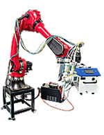
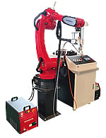
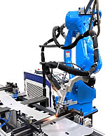
 Робот для сварки 2550

GRBL где хранится файл настроек config.h
Файл настроек config.h прошивки GRBL хранится исходниках в папке grbl/grbl/config.h
/*
config.h - compile time configuration
Part of Grbl
Copyright (c) 2012-2016 Sungeun K. Jeon for Gnea Research LLC
Copyright (c) 2009-2011 Simen Svale Skogsrud
Grbl is free software: you can redistribute it and/or modify
it under the terms of the GNU General Public License as published by
the Free Software Foundation, either version 3 of the License, or
(at your option) any later version.
Grbl is distributed in the hope that it will be useful,
but WITHOUT ANY WARRANTY; without even the implied warranty of
MERCHANTABILITY or FITNESS FOR A PARTICULAR PURPOSE. See the
GNU General Public License for more details.
You should have received a copy of the GNU General Public License
along with Grbl. If not, see <http://www.gnu.org/licenses/>.
*/
// Этот файл содержит конфигурацию для дальнейшей компиляции для внутренней системы Grbl. По большей части, пользователям не нужно будет изменять их напрямую, но они здесь для конкретных нужд, т.е. настройка производительности или настройка на нетиповые машины.
// This file contains compile-time configurations for Grbl's internal system. For the most part, users will not need to directly modify these, but they are here for specific needs, i.e. performance tuning or adjusting to non-typical machines.
// ВАЖНО: любые изменения здесь требуют полной перекомпиляции исходного кода для их применения
// IMPORTANT: Any changes here requires a full re-compiling of the source code to propagate them.
#ifndef config_h
#define config_h
#include "grbl.h" // For Arduino IDE compatibility.
// Define CPU pin map and default settings.
// NOTE: OEMs can avoid the need to maintain/update the defaults.h and cpu_map.h files and use only
// one configuration file by placing their specific defaults and pin map at the bottom of this file.
// If doing so, simply comment out these two defines and see instructions below.
#define DEFAULTS_GENERIC
#define CPU_MAP_ATMEGA328P // Arduino Uno CPU
// Serial baud rate
// #define BAUD_RATE 230400
#define BAUD_RATE 115200
// Define realtime command special characters. These characters are 'picked-off' directly from the serial read data stream and are not passed to the grbl line execution parser. Select characters that do not and must not exist in the streamed g-code program. ASCII control characters may be used, if they are available per user setup. Also, extended ASCII codes (>127), which are never in g-code programs, maybe selected for interface programs.
NOTE: If changed, manually update help message in report.c.
#define CMD_RESET 0x18 // ctrl-x.
#define CMD_STATUS_REPORT '?'
#define CMD_CYCLE_START '~'
#define CMD_FEED_HOLD '!'
// NOTE: All override realtime commands must be in the extended ASCII character set, starting at character value 128 (0x80) and up to 255 (0xFF). If the normal set of realtime commands, such as status reports, feed hold, reset, and cycle start, are moved to the extended set space, serial.c's RX ISR will need to be modified to accomodate the change.
// #define CMD_RESET 0x80
// #define CMD_STATUS_REPORT 0x81
// #define CMD_CYCLE_START 0x82
// #define CMD_FEED_HOLD 0x83
#define CMD_SAFETY_DOOR 0x84
#define CMD_JOG_CANCEL 0x85
#define CMD_DEBUG_REPORT 0x86 // Only when DEBUG enabled, sends debug report in '{}' braces.
#define CMD_FEED_OVR_RESET 0x90 // Restores feed override value to 100%.
#define CMD_FEED_OVR_COARSE_PLUS 0x91
#define CMD_FEED_OVR_COARSE_MINUS 0x92
#define CMD_FEED_OVR_FINE_PLUS 0x93
#define CMD_FEED_OVR_FINE_MINUS 0x94
#define CMD_RAPID_OVR_RESET 0x95 // Restores rapid override value to 100%.
#define CMD_RAPID_OVR_MEDIUM 0x96
#define CMD_RAPID_OVR_LOW 0x97
// #define CMD_RAPID_OVR_EXTRA_LOW 0x98 // *NOT SUPPORTED*
#define CMD_SPINDLE_OVR_RESET 0x99 // Restores spindle override value to 100%.
#define CMD_SPINDLE_OVR_COARSE_PLUS 0x9A
#define CMD_SPINDLE_OVR_COARSE_MINUS 0x9B
#define CMD_SPINDLE_OVR_FINE_PLUS 0x9C
#define CMD_SPINDLE_OVR_FINE_MINUS 0x9D
#define CMD_SPINDLE_OVR_STOP 0x9E
#define CMD_COOLANT_FLOOD_OVR_TOGGLE 0xA0
#define CMD_COOLANT_MIST_OVR_TOGGLE 0xA1
// If homing is enabled, homing init lock sets Grbl into an alarm state upon power up. This forces the user to perform the homing cycle (or override the locks) before doing anything else. This is mainly a safety feature to remind the user to home, since position is unknown to Grbl.
#define HOMING_INIT_LOCK // Comment to disable
// Define the homing cycle patterns with bitmasks. The homing cycle first performs a search mode to quickly engage the limit switches, followed by a slower locate mode, and finished by a short pull-off motion to disengage the limit switches. The following HOMING_CYCLE_x defines are executed in order starting with suffix 0 and completes the homing routine for the specified-axes only. If an axis is omitted from the defines, it will not home, nor will the system update its position. Meaning that this allows for users with non-standard cartesian machines, such as a lathe (x then z, with no y), to configure the homing cycle behavior to their needs.
NOTE: The homing cycle is designed to allow sharing of limit pins, if the axes are not in the same cycle, but this requires some pin settings changes in cpu_map.h file. For example, the default homing cycle can share the Z limit pin with either X or Y limit pins, since they are on different cycles. By sharing a pin, this frees up a precious IO pin for other purposes. In theory, all axes limit pins may be reduced to one pin, if all axes are homed with seperate cycles, or vice versa, all three axes on separate pin, but homed in one cycle. Also, it should be noted that the function of hard limits will not be affected by pin sharing.
NOTE: The homing cycle is designed to allow sharing of limit pins, if the axes are not in the same cycle, but this requires some pin settings changes in cpu_map.h file. For example, the default homing cycle can share the Z limit pin with either X or Y limit pins, since they are on different cycles. By sharing a pin, this frees up a precious IO pin for other purposes. In theory, all axes limit pins may be reduced to one pin, if all axes are homed with seperate cycles, or vice versa, all three axes on separate pin, but homed in one cycle. Also, it should be noted that the function of hard limits will not be affected by pin sharing.
NOTE: Defaults are set for a traditional 3-axis CNC machine. Z-axis first to clear, followed by X & Y.
#define HOMING_CYCLE_0 (1<<Z_AXIS) // REQUIRED: First move Z to clear workspace.
#define HOMING_CYCLE_1 ((1<<X_AXIS)|(1<<Y_AXIS)) // OPTIONAL: Then move X,Y at the same time.
// #define HOMING_CYCLE_2 // OPTIONAL: Uncomment and add axes mask to enable
// NOTE: The following are two examples to setup homing for 2-axis machines.
// #define HOMING_CYCLE_0 ((1<<X_AXIS)|(1<<Y_AXIS)) // NOT COMPATIBLE WITH COREXY: Homes both X-Y in one cycle.
// #define HOMING_CYCLE_0 (1<<X_AXIS) // COREXY COMPATIBLE: First home X
// #define HOMING_CYCLE_1 (1<<Y_AXIS) // COREXY COMPATIBLE: Then home Y
// Number of homing cycles performed after when the machine initially jogs to limit switches. This help in preventing overshoot and should improve repeatability. This value should be one or greater.
#define N_HOMING_LOCATE_CYCLE 1 // Integer (1-128)
// Enables single axis homing commands. $HX, $HY, and $HZ for X, Y, and Z-axis homing. The full homing
// cycle is still invoked by the $H command. This is disabled by default. It's here only to address
// users that need to switch between a two-axis and three-axis machine. This is actually very rare.
// If you have a two-axis machine, DON'T USE THIS. Instead, just alter the homing cycle for two-axes.
// #define HOMING_SINGLE_AXIS_COMMANDS // Default disabled. Uncomment to enable.
// After homing, Grbl will set by default the entire machine space into negative space, as is typical for professional CNC machines, regardless of where the limit switches are located. Uncomment this define to force Grbl to always set the machine origin at the homed location despite switch orientation.
// #define HOMING_FORCE_SET_ORIGIN // Uncomment to enable.
// Number of blocks Grbl executes upon startup. These blocks are stored in EEPROM, where the size and addresses are defined in settings.h. With the current settings, up to 2 startup blocks may be stored and executed in order. These startup blocks would typically be used to set the g-code parser state depending on user preferences.
#define N_STARTUP_LINE 2 // Integer (1-2)
// Number of floating decimal points printed by Grbl for certain value types. These settings are determined by realistic and commonly observed values in CNC machines. For example, position values cannot be less than 0.001mm or 0.0001in, because machines can not be physically more precise this. So, there is likely no need to change these, but you can if you need to here.
NOTE: Must be an integer value from 0 to ~4. More than 4 may exhibit round-off errors.
#define N_DECIMAL_COORDVALUE_INCH 4 // Coordinate or position value in inches
#define N_DECIMAL_COORDVALUE_MM 3 // Coordinate or position value in mm
#define N_DECIMAL_RATEVALUE_INCH 1 // Rate or velocity value in in/min
#define N_DECIMAL_RATEVALUE_MM 0 // Rate or velocity value in mm/min
#define N_DECIMAL_SETTINGVALUE 3 // Decimals for floating point setting values
#define N_DECIMAL_RPMVALUE 0 // RPM value in rotations per min.
// If your machine has two limits switches wired in parallel to one axis, you will need to enable this feature. Since the two switches are sharing a single pin, there is no way for Grbl to tell which one is enabled. This option only effects homing, where if a limit is engaged, Grbl will alarm out and force the user to manually disengage the limit switch. Otherwise, if you have one limit switch for each axis, don't enable this option. By keeping it disabled, you can perform a homing cycle while on the limit switch and not have to move the machine off of it.
// #define LIMITS_TWO_SWITCHES_ON_AXES
// Allows GRBL to track and report gcode line numbers. Enabling this means that the planning buffer goes from 16 to 15 to make room for the additional line number data in the plan_block_t struct
// #define USE_LINE_NUMBERS // Disabled by default. Uncomment to enable.
// Upon a successful probe cycle, this option provides immediately feedback of the probe coordinates through an automatically generated message. If disabled, users can still access the last probe coordinates through Grbl '$#' print parameters.
#define MESSAGE_PROBE_COORDINATES // Enabled by default. Comment to disable.
// Enables a second coolant control pin via the mist coolant g-code command M7 on the Arduino Uno analog pin 4. Only use this option if you require a second coolant control pin.
NOTE: The M8 flood coolant control pin on analog pin 3 will still be functional regardless.
// #define ENABLE_M7 // Disabled by default. Uncomment to enable.
// This option causes the feed hold input to act as a safety door switch. A safety door, when triggered,
// immediately forces a feed hold and then safely de-energizes the machine. Resuming is blocked until
// the safety door is re-engaged. When it is, Grbl will re-energize the machine and then resume on the
// previous tool path, as if nothing happened.
// #define ENABLE_SAFETY_DOOR_INPUT_PIN // Default disabled. Uncomment to enable.
// After the safety door switch has been toggled and restored, this setting sets the power-up delay between restoring the spindle and coolant and resuming the cycle.
#define SAFETY_DOOR_SPINDLE_DELAY 4.0 // Float (seconds)
#define SAFETY_DOOR_COOLANT_DELAY 1.0 // Float (seconds)
// Enable CoreXY kinematics. Use ONLY with CoreXY machines.
IMPORTANT: If homing is enabled, you must reconfigure the homing cycle #defines above to
// #define HOMING_CYCLE_0 (1<<X_AXIS) and #define HOMING_CYCLE_1 (1<<Y_AXIS)
// NOTE: This configuration option alters the motion of the X and Y axes to principle of operation defined at (http://corexy.com/theory.html). Motors are assumed to positioned and wired exactly as described, if not, motions may move in strange directions. Grbl requires the CoreXY A and B motors have the same steps per mm internally.
// #define COREXY // Default disabled. Uncomment to enable.
// Inverts pin logic of the control command pins based on a mask. This essentially means you can use normally-closed switches on the specified pins, rather than the default normally-open switches.
NOTE: The top option will mask and invert all control pins. The bottom option is an example of inverting only two control pins, the safety door and reset. See cpu_map.h for other bit definitions.
// #define INVERT_CONTROL_PIN_MASK CONTROL_MASK // Default disabled. Uncomment to disable.
// #define INVERT_CONTROL_PIN_MASK ((1<<CONTROL_SAFETY_DOOR_BIT)|(1<<CONTROL_RESET_BIT)) // Default disabled.
// Inverts select limit pin states based on the following mask. This effects all limit pin functions, such as hard limits and homing. However, this is different from overall invert limits setting. This build option will invert only the limit pins defined here, and then the invert limits setting will be applied to all of them. This is useful when a user has a mixed set of limit pins with both normally-open(NO) and normally-closed(NC) switches installed on their machine.
NOTE: PLEASE DO NOT USE THIS, unless you have a situation that needs it.
// #define INVERT_LIMIT_PIN_MASK ((1<<X_LIMIT_BIT)|(1<<Y_LIMIT_BIT)) // Default disabled. Uncomment to enable.
// Inverts the spindle enable pin from low-disabled/high-enabled to low-enabled/high-disabled. Useful
// for some pre-built electronic boards.
// NOTE: If VARIABLE_SPINDLE is enabled(default), this option has no effect as the PWM output and
// spindle enable are combined to one pin. If you need both this option and spindle speed PWM,
// uncomment the config option USE_SPINDLE_DIR_AS_ENABLE_PIN below.
// #define INVERT_SPINDLE_ENABLE_PIN // Default disabled. Uncomment to enable.
// Inverts the selected coolant pin from low-disabled/high-enabled to low-enabled/high-disabled. Useful
// for some pre-built electronic boards.
// #define INVERT_COOLANT_FLOOD_PIN // Default disabled. Uncomment to enable.
// #define INVERT_COOLANT_MIST_PIN // Default disabled. Note: Enable M7 mist coolant in config.h
// When Grbl powers-cycles or is hard reset with the Arduino reset button, Grbl boots up with no ALARM
// by default. This is to make it as simple as possible for new users to start using Grbl. When homing
// is enabled and a user has installed limit switches, Grbl will boot up in an ALARM state to indicate
// Grbl doesn't know its position and to force the user to home before proceeding. This option forces
// Grbl to always initialize into an ALARM state regardless of homing or not. This option is more for
// OEMs and LinuxCNC users that would like this power-cycle behavior.
// #define FORCE_INITIALIZATION_ALARM // Default disabled. Uncomment to enable.
// At power-up or a reset, Grbl will check the limit switch states to ensure they are not active before initialization. If it detects a problem and the hard limits setting is enabled, Grbl will simply message the user to check the limits and enter an alarm state, rather than idle. Grbl will not throw an alarm message.
#define CHECK_LIMITS_AT_INIT
// ---------------------------------------------------------------------------------------
// ADVANCED CONFIGURATION OPTIONS:
// Enables code for debugging purposes. Not for general use and always in constant flux.
// #define DEBUG // Uncomment to enable. Default disabled.
// Configure rapid, feed, and spindle override settings. These values define the max and min allowable override values and the coarse and fine increments per command received. Please note the allowable values in the descriptions following each define.
#define DEFAULT_FEED_OVERRIDE 100 // 100%. Don't change this value.
#define MAX_FEED_RATE_OVERRIDE 200 // Percent of programmed feed rate (100-255). Usually 120% or 200%
#define MIN_FEED_RATE_OVERRIDE 10 // Percent of programmed feed rate (1-100). Usually 50% or 1%
#define FEED_OVERRIDE_COARSE_INCREMENT 10 // (1-99). Usually 10%.
#define FEED_OVERRIDE_FINE_INCREMENT 1 // (1-99). Usually 1%.
#define DEFAULT_RAPID_OVERRIDE 100 // 100%. Don't change this value.
#define RAPID_OVERRIDE_MEDIUM 50 // Percent of rapid (1-99). Usually 50%.
#define RAPID_OVERRIDE_LOW 25 // Percent of rapid (1-99). Usually 25%.
// #define RAPID_OVERRIDE_EXTRA_LOW 5 // *NOT SUPPORTED* Percent of rapid (1-99). Usually 5%.
#define DEFAULT_SPINDLE_SPEED_OVERRIDE 100 // 100%. Don't change this value.
#define MAX_SPINDLE_SPEED_OVERRIDE 200 // Percent of programmed spindle speed (100-255). Usually 200%.
#define MIN_SPINDLE_SPEED_OVERRIDE 10 // Percent of programmed spindle speed (1-100). Usually 10%.
#define SPINDLE_OVERRIDE_COARSE_INCREMENT 10 // (1-99). Usually 10%.
#define SPINDLE_OVERRIDE_FINE_INCREMENT 1 // (1-99). Usually 1%.
// When a M2 or M30 program end command is executed, most g-code states are restored to their defaults. This compile-time option includes the restoring of the feed, rapid, and spindle speed override values to their default values at program end.
#define RESTORE_OVERRIDES_AFTER_PROGRAM_END // Default enabled. Comment to disable.
// The status report change for Grbl v1.1 and after also removed the ability to disable/enable most data fields from the report. This caused issues for GUI developers, who've had to manage several scenarios and configurations. The increased efficiency of the new reporting style allows for all data fields to be sent without potential performance issues.
NOTE: The options below are here only provide a way to disable certain data fields if a unique situation demands it, but be aware GUIs may depend on this data. If disabled, it may not be compatible.
#define REPORT_FIELD_BUFFER_STATE // Default enabled. Comment to disable.
#define REPORT_FIELD_PIN_STATE // Default enabled. Comment to disable.
#define REPORT_FIELD_CURRENT_FEED_SPEED // Default enabled. Comment to disable.
#define REPORT_FIELD_WORK_COORD_OFFSET // Default enabled. Comment to disable.
#define REPORT_FIELD_OVERRIDES // Default enabled. Comment to disable.
#define REPORT_FIELD_LINE_NUMBERS // Default enabled. Comment to disable.
// Some status report data isn't necessary for realtime, only intermittently, because the values don't change often. The following macros configures how many times a status report needs to be called before the associated data is refreshed and included in the status report. However, if one of these value changes, Grbl will automatically include this data in the next status report, regardless of what the count is at the time. This helps reduce the communication overhead involved with high frequency reporting and agressive streaming. There is also a busy and an idle refresh count, which sets up Grbl to send refreshes more often when its not doing anything important. With a good GUI, this data doesn't need to be refreshed very often, on the order of a several seconds.
NOTE: WCO refresh must be 2 or greater. OVR refresh must be 1 or greater.
#define REPORT_OVR_REFRESH_BUSY_COUNT 20 // (1-255)
#define REPORT_OVR_REFRESH_IDLE_COUNT 10 // (1-255) Must be less than or equal to the busy count
#define REPORT_WCO_REFRESH_BUSY_COUNT 30 // (2-255)
#define REPORT_WCO_REFRESH_IDLE_COUNT 10 // (2-255) Must be less than or equal to the busy count
// The temporal resolution of the acceleration management subsystem. A higher number gives smoother acceleration, particularly noticeable on machines that run at very high feedrates, but may negatively impact performance. The correct value for this parameter is machine dependent, so it's advised to set this only as high as needed. Approximate successful values can widely range from 50 to 200 or more.
NOTE: Changing this value also changes the execution time of a segment in the step segment buffer. When increasing this value, this stores less overall time in the segment buffer and vice versa. Make
// certain the step segment buffer is increased/decreased to account for these changes.
#define ACCELERATION_TICKS_PER_SECOND 100
// Adaptive Multi-Axis Step Smoothing (AMASS) is an advanced feature that does what its name implies,
// smoothing the stepping of multi-axis motions. This feature smooths motion particularly at low step
// frequencies below 10kHz, where the aliasing between axes of multi-axis motions can cause audible
// noise and shake your machine. At even lower step frequencies, AMASS adapts and provides even better
// step smoothing. See stepper.c for more details on the AMASS system works.
#define ADAPTIVE_MULTI_AXIS_STEP_SMOOTHING // Default enabled. Comment to disable.
// Sets the maximum step rate allowed to be written as a Grbl setting. This option enables an error
// check in the settings module to prevent settings values that will exceed this limitation. The maximum
// step rate is strictly limited by the CPU speed and will change if something other than an AVR running
// at 16MHz is used.
// NOTE: For now disabled, will enable if flash space permits.
// #define MAX_STEP_RATE_HZ 30000 // Hz
// By default, Grbl sets all input pins to normal-high operation with their internal pull-up resistors
// enabled. This simplifies the wiring for users by requiring only a switch connected to ground,
// although its recommended that users take the extra step of wiring in low-pass filter to reduce
// electrical noise detected by the pin. If the user inverts the pin in Grbl settings, this just flips
// which high or low reading indicates an active signal. In normal operation, this means the user
// needs to connect a normal-open switch, but if inverted, this means the user should connect a
// normal-closed switch.
// The following options disable the internal pull-up resistors, sets the pins to a normal-low
// operation, and switches must be now connect to Vcc instead of ground. This also flips the meaning
// of the invert pin Grbl setting, where an inverted setting now means the user should connect a
// normal-open switch and vice versa.
// NOTE: All pins associated with the feature are disabled, i.e. XYZ limit pins, not individual axes.
// WARNING: When the pull-ups are disabled, this requires additional wiring with pull-down resistors!
//#define DISABLE_LIMIT_PIN_PULL_UP
//#define DISABLE_PROBE_PIN_PULL_UP
//#define DISABLE_CONTROL_PIN_PULL_UP
// Sets which axis the tool length offset is applied. Assumes the spindle is always parallel with
// the selected axis with the tool oriented toward the negative direction. In other words, a positive
// tool length offset value is subtracted from the current location.
#define TOOL_LENGTH_OFFSET_AXIS Z_AXIS // Default z-axis. Valid values are X_AXIS, Y_AXIS, or Z_AXIS.
// Enables variable spindle output voltage for different RPM values. On the Arduino Uno, the spindle enable pin will output 5V for maximum RPM with 256 intermediate levels and 0V when disabled.
NOTE: IMPORTANT for Arduino Unos! When enabled, the Z-limit pin D11 and spindle enable pin D12 switch!
The hardware PWM output on pin D11 is required for variable spindle output voltages.
#define VARIABLE_SPINDLE // Default enabled. Comment to disable.
// Used by variable spindle output only. This forces the PWM output to a minimum duty cycle when enabled. The PWM pin will still read 0V when the spindle is disabled. Most users will not need this option, but it may be useful in certain scenarios. This minimum PWM settings coincides with the spindle rpm minimum setting, like rpm max to max PWM. This is handy if you need a larger voltage difference between 0V disabled and the voltage set by the minimum PWM for minimum rpm. This difference is 0.02V per PWM value. So, when minimum PWM is at 1, only 0.02 volts separate enabled and disabled. At PWM 5, this would be 0.1V. Keep in mind that you will begin to lose PWM resolution with increased minimum PWM values, since you have less and less range over the total 255 PWM levels to signal different spindle speeds.
NOTE: Compute duty cycle at the minimum PWM by this equation: (% duty cycle)=(SPINDLE_PWM_MIN_VALUE/255)*100
// #define SPINDLE_PWM_MIN_VALUE 5 // Default disabled. Uncomment to enable. Must be greater than zero. Integer (1-255).
// By default on a 328p(Uno), Grbl combines the variable spindle PWM and the enable into one pin to help preserve I/O pins. For certain setups, these may need to be separate pins. This configure option uses the spindle direction pin(D13) as a separate spindle enable pin along with spindle speed PWM on pin D11.
NOTE: This configure option only works with VARIABLE_SPINDLE enabled and a 328p processor (Uno).
NOTE: Without a direction pin, M4 will not have a pin output to indicate a difference with M3.
NOTE: BEWARE! The Arduino bootloader toggles the D13 pin when it powers up. If you flash Grbl with a programmer (you can use a spare Arduino as "Arduino as ISP". Search the web on how to wire this.), this D13 LED toggling should go away. We haven't tested this though. Please report how it goes!
// #define USE_SPINDLE_DIR_AS_ENABLE_PIN // Default disabled. Uncomment to enable.
// Alters the behavior of the spindle enable pin with the USE_SPINDLE_DIR_AS_ENABLE_PIN option . By default,
// Grbl will not disable the enable pin if spindle speed is zero and M3/4 is active, but still sets the PWM
// output to zero. This allows the users to know if the spindle is active and use it as an additional control
// input. However, in some use cases, user may want the enable pin to disable with a zero spindle speed and
// re-enable when spindle speed is greater than zero. This option does that.
// NOTE: Requires USE_SPINDLE_DIR_AS_ENABLE_PIN to be enabled.
// #define SPINDLE_ENABLE_OFF_WITH_ZERO_SPEED // Default disabled. Uncomment to enable.
// With this enabled, Grbl sends back an echo of the line it has received, which has been pre-parsed (spaces removed, capitalized letters, no comments) and is to be immediately executed by Grbl. Echoes will not be
// sent upon a line buffer overflow, but should for all normal lines sent to Grbl. For example, if a user sendss the line 'g1 x1.032 y2.45 (test comment)', Grbl will echo back in the form '[echo: G1X1.032Y2.45]'.
// NOTE: Only use this for debugging purposes!! When echoing, this takes up valuable resources and can effect performance. If absolutely needed for normal operation, the serial write buffer should be greatly increased to help minimize transmission waiting within the serial write protocol.
// #define REPORT_ECHO_LINE_RECEIVED // Default disabled. Uncomment to enable.
// Minimum planner junction speed. Sets the default minimum junction speed the planner plans to at every buffer block junction, except for starting from rest and end of the buffer, which are always zero. This value controls how fast the machine moves through junctions with no regard for acceleration limits or angle between neighboring block line move directions. This is useful for machines that can't tolerate the tool dwelling for a split second, i.e. 3d printers or laser cutters. If used, this value should not be much greater than zero or to the minimum value necessary for the machine to work.
#define MINIMUM_JUNCTION_SPEED 0.0 // (mm/min)
// Sets the minimum feed rate the planner will allow. Any value below it will be set to this minimum
// value. This also ensures that a planned motion always completes and accounts for any floating-point
// round-off errors. Although not recommended, a lower value than 1.0 mm/min will likely work in smaller
// machines, perhaps to 0.1mm/min, but your success may vary based on multiple factors.
#define MINIMUM_FEED_RATE 1.0 // (mm/min)
// Number of arc generation iterations by small angle approximation before exact arc trajectory
// correction with expensive sin() and cos() calcualtions. This parameter maybe decreased if there
// are issues with the accuracy of the arc generations, or increased if arc execution is getting
// bogged down by too many trig calculations.
#define N_ARC_CORRECTION 12 // Integer (1-255)
// The arc G2/3 g-code standard is problematic by definition. Radius-based arcs have horrible numerical
// errors when arc at semi-circles(pi) or full-circles(2*pi). Offset-based arcs are much more accurate
// but still have a problem when arcs are full-circles (2*pi). This define accounts for the floating
// point issues when offset-based arcs are commanded as full circles, but get interpreted as extremely
// small arcs with around machine epsilon (1.2e-7rad) due to numerical round-off and precision issues.
// This define value sets the machine epsilon cutoff to determine if the arc is a full-circle or not.
// NOTE: Be very careful when adjusting this value. It should always be greater than 1.2e-7 but not too
// much greater than this. The default setting should capture most, if not all, full arc error situations.
#define ARC_ANGULAR_TRAVEL_EPSILON 5E-7 // Float (radians)
// Time delay increments performed during a dwell. The default value is set at 50ms, which provides
// a maximum time delay of roughly 55 minutes, more than enough for most any application. Increasing
// this delay will increase the maximum dwell time linearly, but also reduces the responsiveness of
// run-time command executions, like status reports, since these are performed between each dwell
// time step. Also, keep in mind that the Arduino delay timer is not very accurate for long delays.
#define DWELL_TIME_STEP 50 // Integer (1-255) (milliseconds)
// Creates a delay between the direction pin setting and corresponding step pulse by creating
// another interrupt (Timer2 compare) to manage it. The main Grbl interrupt (Timer1 compare)
// sets the direction pins, and does not immediately set the stepper pins, as it would in
// normal operation. The Timer2 compare fires next to set the stepper pins after the step
// pulse delay time, and Timer2 overflow will complete the step pulse, except now delayed
// by the step pulse time plus the step pulse delay. (Thanks langwadt for the idea!)
// NOTE: Uncomment to enable. The recommended delay must be > 3us, and, when added with the
// user-supplied step pulse time, the total time must not exceed 127us. Reported successful
// values for certain setups have ranged from 5 to 20us.
// #define STEP_PULSE_DELAY 10 // Step pulse delay in microseconds. Default disabled.
// The number of linear motions in the planner buffer to be planned at any give time. The vast
// majority of RAM that Grbl uses is based on this buffer size. Only increase if there is extra
// available RAM, like when re-compiling for a Mega2560. Or decrease if the Arduino begins to
// crash due to the lack of available RAM or if the CPU is having trouble keeping up with planning
// new incoming motions as they are executed.
// #define BLOCK_BUFFER_SIZE 16 // Uncomment to override default in planner.h.
// Governs the size of the intermediary step segment buffer between the step execution algorithm
// and the planner blocks. Each segment is set of steps executed at a constant velocity over a
// fixed time defined by ACCELERATION_TICKS_PER_SECOND. They are computed such that the planner
// block velocity profile is traced exactly. The size of this buffer governs how much step
// execution lead time there is for other Grbl processes have to compute and do their thing
// before having to come back and refill this buffer, currently at ~50msec of step moves.
// #define SEGMENT_BUFFER_SIZE 6 // Uncomment to override default in stepper.h.
// Line buffer size from the serial input stream to be executed. Also, governs the size of
// each of the startup blocks, as they are each stored as a string of this size. Make sure
// to account for the available EEPROM at the defined memory address in settings.h and for
// the number of desired startup blocks.
// NOTE: 80 characters is not a problem except for extreme cases, but the line buffer size
// can be too small and g-code blocks can get truncated. Officially, the g-code standards
// support up to 256 characters. In future versions, this default will be increased, when
// we know how much extra memory space we can re-invest into this.
// #define LINE_BUFFER_SIZE 80 // Uncomment to override default in protocol.h
// Serial send and receive buffer size. The receive buffer is often used as another streaming
// buffer to store incoming blocks to be processed by Grbl when its ready. Most streaming
// interfaces will character count and track each block send to each block response. So,
// increase the receive buffer if a deeper receive buffer is needed for streaming and avaiable
// memory allows. The send buffer primarily handles messages in Grbl. Only increase if large
// messages are sent and Grbl begins to stall, waiting to send the rest of the message.
// NOTE: Grbl generates an average status report in about 0.5msec, but the serial TX stream at
// 115200 baud will take 5 msec to transmit a typical 55 character report. Worst case reports are
// around 90-100 characters. As long as the serial TX buffer doesn't get continually maxed, Grbl
// will continue operating efficiently. Size the TX buffer around the size of a worst-case report.
// #define RX_BUFFER_SIZE 128 // (1-254) Uncomment to override defaults in serial.h
// #define TX_BUFFER_SIZE 100 // (1-254)
// A simple software debouncing feature for hard limit switches. When enabled, the interrupt
// monitoring the hard limit switch pins will enable the Arduino's watchdog timer to re-check
// the limit pin state after a delay of about 32msec. This can help with CNC machines with
// problematic false triggering of their hard limit switches, but it WILL NOT fix issues with
// electrical interference on the signal cables from external sources. It's recommended to first
// use shielded signal cables with their shielding connected to ground (old USB/computer cables
// work well and are cheap to find) and wire in a low-pass circuit into each limit pin.
// #define ENABLE_SOFTWARE_DEBOUNCE // Default disabled. Uncomment to enable.
// Configures the position after a probing cycle during Grbl's check mode. Disabled sets
// the position to the probe target, when enabled sets the position to the start position.
// #define SET_CHECK_MODE_PROBE_TO_START // Default disabled. Uncomment to enable.
// Force Grbl to check the state of the hard limit switches when the processor detects a pin
// change inside the hard limit ISR routine. By default, Grbl will trigger the hard limits
// alarm upon any pin change, since bouncing switches can cause a state check like this to
// misread the pin. When hard limits are triggered, they should be 100% reliable, which is the
// reason that this option is disabled by default. Only if your system/electronics can guarantee
// that the switches don't bounce, we recommend enabling this option. This will help prevent
// triggering a hard limit when the machine disengages from the switch.
// NOTE: This option has no effect if SOFTWARE_DEBOUNCE is enabled.
// #define HARD_LIMIT_FORCE_STATE_CHECK // Default disabled. Uncomment to enable.
// Adjusts homing cycle search and locate scalars. These are the multipliers used by Grbl's
// homing cycle to ensure the limit switches are engaged and cleared through each phase of
// the cycle. The search phase uses the axes max-travel setting times the SEARCH_SCALAR to
// determine distance to look for the limit switch. Once found, the locate phase begins and
// uses the homing pull-off distance setting times the LOCATE_SCALAR to pull-off and re-engage
// the limit switch.
// NOTE: Both of these values must be greater than 1.0 to ensure proper function.
// #define HOMING_AXIS_SEARCH_SCALAR 1.5 // Uncomment to override defaults in limits.c.
// #define HOMING_AXIS_LOCATE_SCALAR 10.0 // Uncomment to override defaults in limits.c.
// Enable the '$RST=*', '$RST=$', and '$RST=#' eeprom restore commands. There are cases where
// these commands may be undesirable. Simply comment the desired macro to disable it.
// NOTE: See SETTINGS_RESTORE_ALL macro for customizing the `$RST=*` command.
#define ENABLE_RESTORE_EEPROM_WIPE_ALL // '$RST=*' Default enabled. Comment to disable.
#define ENABLE_RESTORE_EEPROM_DEFAULT_SETTINGS // '$RST=$' Default enabled. Comment to disable.
#define ENABLE_RESTORE_EEPROM_CLEAR_PARAMETERS // '$RST=#' Default enabled. Comment to disable.
// Defines the EEPROM data restored upon a settings version change and `$RST=*` command. Whenever the
// the settings or other EEPROM data structure changes between Grbl versions, Grbl will automatically
// wipe and restore the EEPROM. This macro controls what data is wiped and restored. This is useful
// particularily for OEMs that need to retain certain data. For example, the BUILD_INFO string can be
// written into the Arduino EEPROM via a seperate .INO sketch to contain product data. Altering this
// macro to not restore the build info EEPROM will ensure this data is retained after firmware upgrades.
// NOTE: Uncomment to override defaults in settings.h
// #define SETTINGS_RESTORE_ALL (SETTINGS_RESTORE_DEFAULTS | SETTINGS_RESTORE_PARAMETERS | SETTINGS_RESTORE_STARTUP_LINES | SETTINGS_RESTORE_BUILD_INFO)
// Enable the '$I=(string)' build info write command. If disabled, any existing build info data must
// be placed into EEPROM via external means with a valid checksum value. This macro option is useful
// to prevent this data from being over-written by a user, when used to store OEM product data.
// NOTE: If disabled and to ensure Grbl can never alter the build info line, you'll also need to enable
// the SETTING_RESTORE_ALL macro above and remove SETTINGS_RESTORE_BUILD_INFO from the mask.
// NOTE: See the included grblWrite_BuildInfo.ino example file to write this string seperately.
#define ENABLE_BUILD_INFO_WRITE_COMMAND // '$I=' Default enabled. Comment to disable.
// AVR processors require all interrupts to be disabled during an EEPROM write. This includes both
// the stepper ISRs and serial comm ISRs. In the event of a long EEPROM write, this ISR pause can
// cause active stepping to lose position and serial receive data to be lost. This configuration
// option forces the planner buffer to completely empty whenever the EEPROM is written to prevent
// any chance of lost steps.
// However, this doesn't prevent issues with lost serial RX data during an EEPROM write, especially
// if a GUI is premptively filling up the serial RX buffer simultaneously. It's highly advised for
// GUIs to flag these gcodes (G10,G28.1,G30.1) to always wait for an 'ok' after a block containing
// one of these commands before sending more data to eliminate this issue.
// NOTE: Most EEPROM write commands are implicitly blocked during a job (all '$' commands). However,
// coordinate set g-code commands (G10,G28/30.1) are not, since they are part of an active streaming
// job. At this time, this option only forces a planner buffer sync with these g-code commands.
#define FORCE_BUFFER_SYNC_DURING_EEPROM_WRITE // Default enabled. Comment to disable.
// In Grbl v0.9 and prior, there is an old outstanding bug where the `WPos:` work position reported
// may not correlate to what is executing, because `WPos:` is based on the g-code parser state, which
// can be several motions behind. This option forces the planner buffer to empty, sync, and stop
// motion whenever there is a command that alters the work coordinate offsets `G10,G43.1,G92,G54-59`.
// This is the simplest way to ensure `WPos:` is always correct. Fortunately, it's exceedingly rare
// that any of these commands are used need continuous motions through them.
#define FORCE_BUFFER_SYNC_DURING_WCO_CHANGE // Default enabled. Comment to disable.
// By default, Grbl disables feed rate overrides for all G38.x probe cycle commands. Although this
// may be different than some pro-class machine control, it's arguable that it should be this way.
// Most probe sensors produce different levels of error that is dependent on rate of speed. By
// keeping probing cycles to their programmed feed rates, the probe sensor should be a lot more
// repeatable. If needed, you can disable this behavior by uncommenting the define below.
// #define ALLOW_FEED_OVERRIDE_DURING_PROBE_CYCLES // Default disabled. Uncomment to enable.
// Enables and configures parking motion methods upon a safety door state. Primarily for OEMs
// that desire this feature for their integrated machines. At the moment, Grbl assumes that
// the parking motion only involves one axis, although the parking implementation was written
// to be easily refactored for any number of motions on different axes by altering the parking
// source code. At this time, Grbl only supports parking one axis (typically the Z-axis) that
// moves in the positive direction upon retracting and negative direction upon restoring position.
// The motion executes with a slow pull-out retraction motion, power-down, and a fast park.
// Restoring to the resume position follows these set motions in reverse: fast restore to
// pull-out position, power-up with a time-out, and plunge back to the original position at the
// slower pull-out rate.
// NOTE: Still a work-in-progress. Machine coordinates must be in all negative space and
// does not work with HOMING_FORCE_SET_ORIGIN enabled. Parking motion also moves only in
// positive direction.
// #define PARKING_ENABLE // Default disabled. Uncomment to enable
// Configure options for the parking motion, if enabled.
#define PARKING_AXIS Z_AXIS // Define which axis that performs the parking motion
#define PARKING_TARGET -5.0 // Parking axis target. In mm, as machine coordinate [-max_travel,0].
#define PARKING_RATE 500.0 // Parking fast rate after pull-out in mm/min.
#define PARKING_PULLOUT_RATE 100.0 // Pull-out/plunge slow feed rate in mm/min.
#define PARKING_PULLOUT_INCREMENT 5.0 // Spindle pull-out and plunge distance in mm. Incremental distance.
// Must be positive value or equal to zero.
// Enables a special set of M-code commands that enables and disables the parking motion.
// These are controlled by `M56`, `M56 P1`, or `M56 Px` to enable and `M56 P0` to disable.
// The command is modal and will be set after a planner sync. Since it is g-code, it is
// executed in sync with g-code commands. It is not a real-time command.
// NOTE: PARKING_ENABLE is required. By default, M56 is active upon initialization. Use
// DEACTIVATE_PARKING_UPON_INIT to set M56 P0 as the power-up default.
// #define ENABLE_PARKING_OVERRIDE_CONTROL // Default disabled. Uncomment to enable
// #define DEACTIVATE_PARKING_UPON_INIT // Default disabled. Uncomment to enable.
// This option will automatically disable the laser during a feed hold by invoking a spindle stop
// override immediately after coming to a stop. However, this also means that the laser still may
// be reenabled by disabling the spindle stop override, if needed. This is purely a safety feature
// to ensure the laser doesn't inadvertently remain powered while at a stop and cause a fire.
#define DISABLE_LASER_DURING_HOLD // Default enabled. Comment to disable.
// This feature alters the spindle PWM/speed to a nonlinear output with a simple piecewise linear
// curve. Useful for spindles that don't produce the right RPM from Grbl's standard spindle PWM
// linear model. Requires a solution by the 'fit_nonlinear_spindle.py' script in the /doc/script
// folder of the repo. See file comments on how to gather spindle data and run the script to
// generate a solution.
// #define ENABLE_PIECEWISE_LINEAR_SPINDLE // Default disabled. Uncomment to enable.
// N_PIECES, RPM_MAX, RPM_MIN, RPM_POINTxx, and RPM_LINE_XX constants are all set and given by
// the 'fit_nonlinear_spindle.py' script solution. Used only when ENABLE_PIECEWISE_LINEAR_SPINDLE
// is enabled. Make sure the constant values are exactly the same as the script solution.
// NOTE: When N_PIECES < 4, unused RPM_LINE and RPM_POINT defines are not required and omitted.
#define N_PIECES 4 // Integer (1-4). Number of piecewise lines used in script solution.
#define RPM_MAX 11686.4 // Max RPM of model. $30 > RPM_MAX will be limited to RPM_MAX.
#define RPM_MIN 202.5 // Min RPM of model. $31 < RPM_MIN will be limited to RPM_MIN.
#define RPM_POINT12 6145.4 // Used N_PIECES >=2. Junction point between lines 1 and 2.
#define RPM_POINT23 9627.8 // Used N_PIECES >=3. Junction point between lines 2 and 3.
#define RPM_POINT34 10813.9 // Used N_PIECES = 4. Junction point between lines 3 and 4.
#define RPM_LINE_A1 3.197101e-03 // Used N_PIECES >=1. A and B constants of line 1.
#define RPM_LINE_B1 -3.526076e-1
#define RPM_LINE_A2 1.722950e-2 // Used N_PIECES >=2. A and B constants of line 2.
#define RPM_LINE_B2 8.588176e+01
#define RPM_LINE_A3 5.901518e-02 // Used N_PIECES >=3. A and B constants of line 3.
#define RPM_LINE_B3 4.881851e+02
#define RPM_LINE_A4 1.203413e-01 // Used N_PIECES = 4. A and B constants of line 4.
#define RPM_LINE_B4 1.151360e+03
/* ---------------------------------------------------------------------------------------
This optional dual axis feature is primarily for the homing cycle to locate two sides of
a dual-motor gantry independently, i.e. self-squaring. This requires an additional limit
switch for the cloned motor. To self square, both limit switches on the cloned axis must
be physically positioned to trigger when the gantry is square. Highly recommend keeping
the motors always enabled to ensure the gantry stays square with the $1=255 setting.
For Grbl on the Arduino Uno, the cloned axis limit switch must to be shared with and
wired with z-axis limit pin due to the lack of available pins. The homing cycle must home
the z-axis and cloned axis in different cycles, which is already the default config.
The dual axis feature works by cloning an axis step output onto another pair of step
and direction pins. The step pulse and direction of the cloned motor can be set
independently of the main axis motor. However to save precious flash and memory, this
dual axis feature must share the same settings (step/mm, max speed, acceleration) as the
parent motor. This is NOT a feature for an independent fourth axis. Only a motor clone.
WARNING: Make sure to test the directions of your dual axis motors! They must be setup
to move the same direction BEFORE running your first homing cycle or any long motion!
Motors moving in opposite directions can cause serious damage to your machine! Use this
dual axis feature at your own risk.
*/
// NOTE: This feature requires approximately 400 bytes of flash. Certain configurations can
// run out of flash to fit on an Arduino 328p/Uno. Only X and Y axes are supported. Variable
// spindle/laser mode IS supported, but only for one config option. Core XY, spindle direction
// pin, and M7 mist coolant are disabled/not supported.
// #define ENABLE_DUAL_AXIS // Default disabled. Uncomment to enable.
// Select the one axis to mirror another motor. Only X and Y axis is supported at this time.
#define DUAL_AXIS_SELECT X_AXIS // Must be either X_AXIS or Y_AXIS
// To prevent the homing cycle from racking the dual axis, when one limit triggers before the
// other due to switch failure or noise, the homing cycle will automatically abort if the second
// motor's limit switch does not trigger within the three distance parameters defined below.
// Axis length percent will automatically compute a fail distance as a percentage of the max
// travel of the other non-dual axis, i.e. if dual axis select is X_AXIS at 5.0%, then the fail
// distance will be computed as 5.0% of y-axis max travel. Fail distance max and min are the
// limits of how far or little a valid fail distance is.
#define DUAL_AXIS_HOMING_FAIL_AXIS_LENGTH_PERCENT 5.0 // Float (percent)
#define DUAL_AXIS_HOMING_FAIL_DISTANCE_MAX 25.0 // Float (mm)
#define DUAL_AXIS_HOMING_FAIL_DISTANCE_MIN 2.5 // Float (mm)
// Dual axis pin configuration currently supports two shields. Uncomment the shield you want,
// and comment out the other one(s).
// NOTE: Protoneer CNC Shield v3.51 has A.STP and A.DIR wired to pins A4 and A3 respectively.
// The variable spindle (i.e. laser mode) build option works and may be enabled or disabled.
// Coolant pin A3 is moved to D13, replacing spindle direction.
#define DUAL_AXIS_CONFIG_PROTONEER_V3_51 // Uncomment to select. Comment other configs.
// NOTE: Arduino CNC Shield Clone (Originally Protoneer v3.0) has A.STP and A.DIR wired to
// D12 and D13, respectively. With the limit pins and stepper enable pin on this same port,
// the spindle enable pin had to be moved and spindle direction pin deleted. The spindle
// enable pin now resides on A3, replacing coolant enable. Coolant enable is bumped over to
// pin A4. Spindle enable is used far more and this pin setup helps facilitate users to
// integrate this feature without arguably too much work.
// Variable spindle (i.e. laser mode) does NOT work with this shield as configured. While
// variable spindle technically can work with this shield, it requires too many changes for
// most user setups to accomodate. It would best be implemented by sharing all limit switches
// on pins D9/D10 (as [X1,Z]/[X2,Y] or [X,Y2]/[Y1,Z]), home each axis independently, and
// updating lots of code to ensure everything is running correctly.
// #define DUAL_AXIS_CONFIG_CNC_SHIELD_CLONE // Uncomment to select. Comment other configs.
/* ---------------------------------------------------------------------------------------
OEM Single File Configuration Option
Instructions: Paste the cpu_map and default setting definitions below without an enclosing
#ifdef. Comment out the CPU_MAP_xxx and DEFAULT_xxx defines at the top of this file, and
the compiler will ignore the contents of defaults.h and cpu_map.h and use the definitions
below.
*/
// Paste CPU_MAP definitions here.
// Paste default settings definitions here.
#endif